

In this publication, the first in a series of "hands on lab" articles, we are going to see how to access the firmware of a device to begin to understand a little of the exciting world of IoT hacking.
This is a Gateway that we use to send the telemetry of our Zigbee sensors, very common in home automation and Internet of Things, to "the cloud".
Entry points to the device
Sometimes you can access a device through an open port (http, ssh), or simply download the firmware from the manufacturer's website. Other times, however, it can only be obtained by "dumping" it from a flash memory chip, or through On-Chip Debugging (OCD) interfaces, which some manufacturers leave on their device boards as diagnostic points.
There are several protocols for OCD, such as JTAG, I2C, SWD or UART, and each of them is usually presented on the board as a configuration of 2, 4 or more connection "points". The idea is to try to identify them visually, and then, with a multimeter, an oscilloscope, or a logic analyser, determine which point is which ("RX", "TX", "GND", etc.).
Recon: obtaining information about the device
For visual identification of these connectors, there is a fantastic tool that allows you to get pictures of the inside of the device without having to open it. This is the Federal Communications Commission (FCC) database, where device manufacturers include documentation, user manuals and pictures. The FCCID identifier is usually found on the side labels or on the bottom of the device.
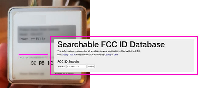
We search for our gateway ID at https://fccid.io/, and the following results, among others, appear:
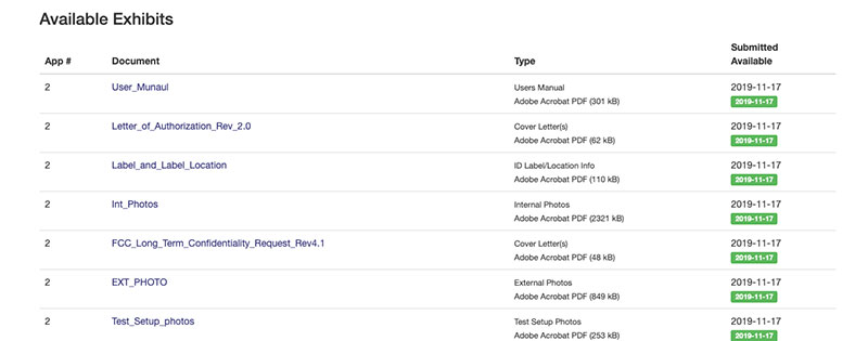
The one we are interested in now is the Int_Photos document. In it we are going to have some images with quite a lot of detail about the inside of the device:
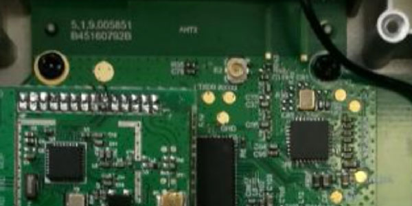
We can distinguish several groups of pins, which could well be JTAG or UART interfaces.
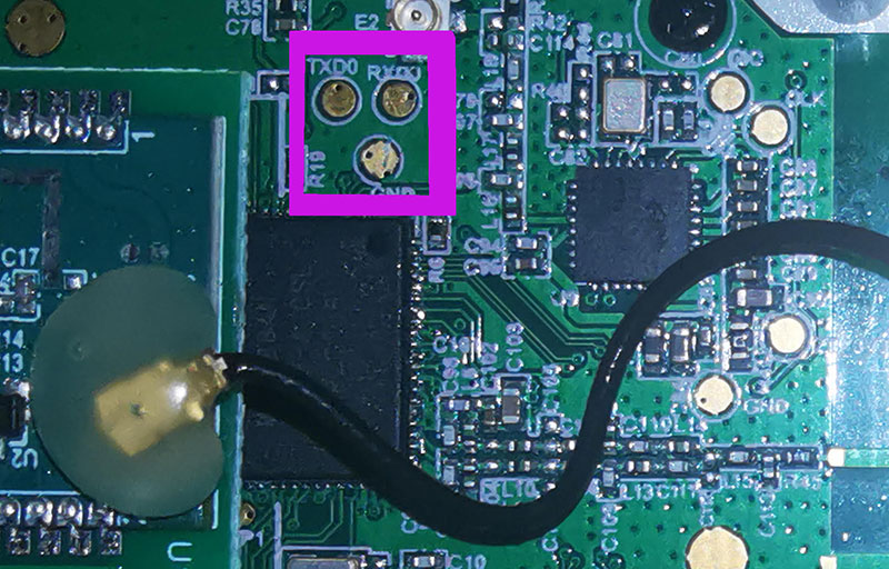
If we look at the group of three gold pins in the centre of the picture, we can distinguish not very clearly the words TXD0 and GND. The third one is not visible at all.
Our toolkit
To confirm this, we will open the device and connect to the presumed UART interface. In IoT Hardware Hacking, the Swiss Army knife and guitar picks are like the locksmith's X-rays.
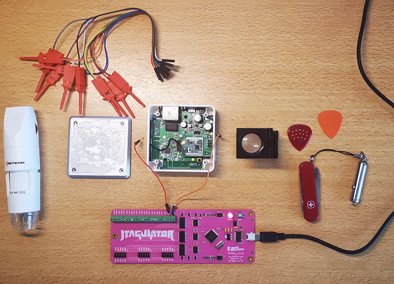
Once opened, with a good magnifying glass or a small WiFi microscope we can observe the board in more detail, clearly seeing that there is a TXD0, a RXD0 and a GND port.
*NOTE: as we are going to work with the gateway connected to the electrical current, we must measure with a multimeter the pins we are going to check, to be sure of the voltage and avoid damage to the equipment or to ourselves.
To identify the different pins, you can use many tools at different prices. The inexpensive FT232H (about 20€), the Bus Pirate, or in our case, the JTagulator, which is a bit more expensive, but it is worth it if you are going to use it a lot, as it is very convenient and versatile: it can be used for JTAG, UART, SWD, etc.
Searching for UART input
We connect the tool to our computer through a serial port, and we can immediately see that there is a device in /dev/ that we can connect to with the "screen" command:
ipmoreno$ ls /dev/tty.*
/dev/tty.Bluetooth-Incoming-Port /dev/tty.usbserial-AL05RPEH

ipmoreno$ sudo screen /dev/tty.usbserial-AL05RPEH 115200

                                  UU LLL
 JJJJ TTTTTTTTT AAAAAAA GGGGGGGGGGGGGGGGGGG UUUU LLL AAAAAAA TTTTTTTT OOOOOOO RRRRRRRRRRRRRRRRR
 JJJJJ TTTTTTTTT AAAAAAAA GGGGGGGGGGG UUUU LLL AAAAAAAA TTTTTTTT OOOOOOO RRRRRRRRRRRRRR
 JJJJJ TTTT AAAAAAAA GGG UUU UUU UUUU LLL AAA AAA AAA TTT OOOO OOO RRR RRR RRR
 JJJJJ TTTT AAA AAA AAA GGG GGG GGG UUUU UUUU UUUU LLL AAA AAA AAA TTT OOO OOO OOO RRRRRRRRRRRRRR
 JJJJJ TTTT AAA AAA AA GGGGGGGGGGGGGGG UUUUUUUU LLLLLLLLLLLL AAAA TTT OOOOOOOOO RRR RRR RRR
  JJJ TTTT AAA AA GGGGGGGGGGGGGGG UUUUUUUU LLLLLLLLLLL AAA TTT OOOOOOOOO RRR RRR RRR
  JJJ TT GGG AAA RR RRR RRR
 JJJ GG AA RRR
JJJ G G A RR


           Welcome to JTAGulator. Press 'H' for available commands.
         Warning: Use of this tool may affect target system behavior!
Feeling the power of this cool banner, we can start working with our target. As we are going to identify UART pins we select the "U" option from the menu, but not before selecting the voltage (3.3 volts).
> H
Target Interfaces:
J JTAG
U UART
G GPIO
S SWD

General Commands:
V Set target I/O voltage
I Display version information
H Display available commands
In the UART menu, we press the "U" command again, to identify the TX and RX pins by brute force. In this case we only have two, so the "brute force" is limited to looking for a suitable transmission speed.
TXD: 0
RXD: 1
Baud: 38400
Data: ... [ F9 FC ]

TXD: 0
RXD: 1
Baud: 57600
Data: ..login: [ 0D 0A 6C 6F 67 69 6E 3A 20 ]

TXD: 0
RXD: 1
Baud: 115200
Data: . [ F8 ]

UART scan complete.
As they say in these cases... Bingo: it seems that the pins are correct and that they are transmitting at 57600 baud, and in fact we see the word "login: " which means that there is a Shell waiting for us.
Now we use the "P" command ("UART Passthrough").
Enter TXD pin [0]: 0
Enter RXD pin [1]: 1
Enter baud rate [0]: 57600
Enable local echo? [y/N]:
Entering UART passthrough! Press Ctrl-X to exit...
As I don't see anything coming from the pins, I turn the gateway off and on, and we start to see the boot process messages:
[ 0.840000] VFS: Mounted root (squashfs filesystem) readonly on device 31:5.
[ 0.860000] Freeing unused kernel memory: 172K (80325000 - 80350000)
[ 2.690000] init: Console is alive
[ 2.700000] init: - watchdog -
...
[ 22.660000] |--------------------------------------------------------|
[ 22.680000] |------------xxxxxx-version:x.x--------------------------|
[ 22.690000] |(c) 20xx xxx -------------------------------------------|
[ 22.730000] |--------------------------------------------------------|
We press "enter" a couple of times and we get the much sought after login prompt...
login: root
passwd:
We tried various login and password combinations, but to no avail. We checked the debug messages for something that would allow us to enter the shell.
[ 6.850000] random: procd urandom read with 10 bits of entropy available
Press the [f] key and hit [enter] to enter failsafe mode
Press the [1], [2], [3] or [4] key and hit [enter] to select the debug level
...
The failsafe mode
It doesn't take long to find some messages indicating how to enter failsafe mode, which usually has "root" privileges. We switch off and on again, but now we press "f" when the message appears, and... [fingers crossed]:
Press the [f] key and hit [enter] to enter failsafe mode
Press the [1], [2], [3] or [4] key and hit [enter] to select the debug level
f
- failsafe -

================= FAILSAFE MODE active ================
special commands:
* firstboot reset settings to factory defaults
* mount_root mount root-partition with config files

=======================================================

root@(none):/#
The prompt appears again, but this time authenticated as root! Another saying that will make you feel like a real hacker (the kind that wears a hood or a beanie) is: "We're in!
Now, we can scan all directories, configuration files, open network connections, etc. and look for vulnerabilities in the administration web or in any of the executables running inside the gateway. Discovering a vulnerability would allow us to not only control our gateway, but any other gateway with the same firmware version.
Obviously, we only do this kind of analysis for research purposes and to help customers who request it, so that they can make their products more secure. I hope you found this brief introduction interesting, and that it might even inspire some of you to take the next step towards IoT hacking.